| The ControlLogix driver has been
updated to support full gateway operation through your ControlLogix processor. The concept behind routing is to provide a
means of communicating with a remote ControlLogix backplane over various networks. Routing
can be thought of as a bridge between your local ControlLogix backplane and a remote
ControlLogix backplane even if they are on two different fieldbus networks. Access to a
remote (destination) backplane allows for direct communication with the following modules
located on this backplane:
Remote Modules
Accessible Via Routing:
- ControlLogix 5000 processor for ControlLogix applications
- 1756-DHRIO interface module for DH+ Gateway applications
- 1756-CNB or 1756-CNBR interface module for ControlNet Gateway
applications
A routing path is a series of
backplane hops, with the last hop pointing to the destination backplane. Each hop requires
a ControlLogix backplane (not a ControlLogix processor). An individual hop can utilize one
of the following networks as its medium:
Networks Supported:
- ControlNet
- DH+
- Ethernet (EtherNet/IP)
Application Notes
1) Messages cannot be routed in or out
of the same interface module channel more than once within the path. Doing so results in
CIP Error 0x01 Ext. Error 0x100B.
2) For multiple channel interface modules, messages cannot be routed into and then
immediately out of that same module (using different channels), regardless if the message
is directed to the backplane first or avoids the backplane all together. As previously
mentioned, the latter is not supported since each hop requires a ControlLogix backplane.
An example would be to route a DH+ message from one DH+ link (ie. Channel A of 1756-DHRIO)
to another DH+ link (ie. Channel B of same 1756-DHRIO) through one 1756-DHRIO interface
module This is commonly referred to as Remote DH+ messaging and is not supported.
Connection Path Specification
The routing path is specified in the Device ID. As with non-routing applications,
communication originates from the ControlLogix Ethernet driver on the PC and is directed
at the local ControlLogix Ethernet Interface (1756-ENET). Once at this local 1756-ENET,
the Device ID specifies a way out of the module and onto the backplane, just like with
non-routing applications. From there the routing path will direct the message to the
desired ControlLogix backplane. The remainder of the Device ID will determine what device
to communicate with (ControlLogix processor, DH+ node, ControlNet node). The routing path
specification begins and ends with the left and right bracket respectively ([, ]). The
path itself is a series of port/link address pairs, identical to the Communication Path
syntax in RSLogix 5000 Message Configuration dialog. A port describes a way out of a
device via a network or backplane. A link address is a destination address and is commonly
referred to as a node id or next hop.
| Designator |
Description |
Formats |
Valid Values |
| Port ID |
Specifies a way out of the interface module
in question. See Ports below. |
Decimal |
0 - 65535 |
| Link Address |
If the corresponding port is the backplane,
then the link address is the slot number of the interface module you wish to go out of. |
Decimal |
0 - 255 |
|
If the corresponding port is an interface module port, then the link address
specifies a destination node as follows.
- DH+/ControlNet: node id
-1756-ENET module: IP address. |
|
|
The general syntax for the
connection path is shown in bold below.
Single Hop
IP Address,Port ID0, [Link Address0, Port ID1, Link Address1, Port ID2], Link
Address2
Multi-Hop (N Hops)
IP Address,Port ID0, [Link Address0, Port ID1, Link Address1, Port ID2, Link
Address2, ... Port ID(N+1), Link Address(N+1), Port ID(N+2)], Link Address(N+2)
Note: The last Port ID in the path (Port ID2 and Port ID(N+2) for single hop and
multi-hop respectively) must be 1 (port for backplane).
The Port ID0 must be 1 (port for backplane), Link Address2 and Link Address(N+2) are the
slot numbers of the remote Logix processor/1756-DHRIO module/1756-CNB module.
Ports
| Interface Module
|
Port 1 |
Port 2 |
Port 3 |
| 1756-ENET |
Backplane |
Ethernet
Network |
N/A |
| 1756-DHRIO |
Backplane |
DH+ Network
on Ch. A |
DH+ Network
on Ch. B |
| 1756-CNB |
Backplane |
ControlNet
Network |
N/A |
Examples
Due to the complex nature of this feature, examples may be the best tutorial. The examples
below will include the entire the Device ID minus the IP of the local 1756-ENET. Again,
the perspective of the Device ID/Routing Path is from the local 1756-ENET module. Hop
descriptions are in the form: Link Address(N), Port ID(N+1), Link Address(N+1), Port
ID(N+2). See Connection Path Specification above for help. For further details on building
a connection/routing path, refer to Allen-Bradley Publication 1756-6.5.14, pp. 4-5 through
4-8.
Key:
Green = Ethernet
Blue = DH+
Orange = ControlNet
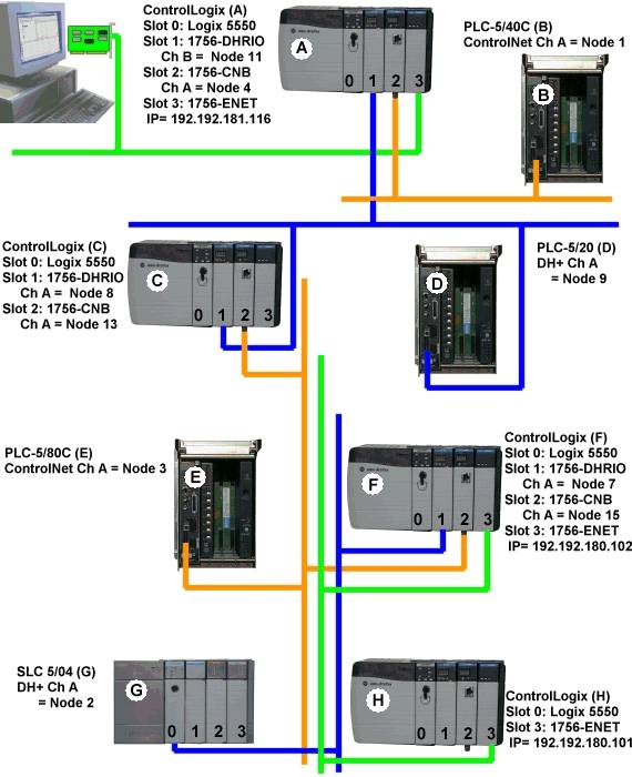
Example 1) Logix5550 to PLC-5 via DH+ Gateway
| Destination Node
|
Model |
Routing |
Device ID less IP |
| PLC-5/20 (D) |
DH+ Gateway |
No |
1,1.B.9 |
Example 2) Logix5550 to PLC-5C via
CN Gateway.
| Destination Node
|
Model |
Routing |
Device ID less IP |
| PLC-5/40C (B) |
CN Gateway |
No |
1,2.A.1 |
Example 3) Logix5550 to Logix5550
via Routing over DH+.
| Destination Node
|
Model |
Routing |
Device ID less IP |
| Logix5550 (C) |
ControlLogix 5550 |
Yes |
1,[1,2,8,1],0 |
Routing Path Breakdown
| Hop |
Segment |
Description |
| 1 |
1,2,8,1 |
Slot 1 (DHRIO) ->
Port 2 (DH+ Ch A) -> DH+ Node 8 -> Logix C Backplane |
Example 4) Logix5550 to PLC-5C via
CN Gateway, Routing over DH+.
| Destination Node
|
Model |
Routing |
Device ID less IP |
| PLC-5/80C (E) |
CN Gateway |
Yes |
1,[1,2,8,1],2.A.3 |
Routing Path Breakdown
| Hop |
Segment |
Description |
| 1 |
1,2,8,1 |
Slot 1 (DHRIO) ->
Port 2 (DH+ Ch A) -> DH+ Node 8 -> Logix C Backplane |
Example 5) Logix5550 to Logix5550
via Routing over DH+, ControlNet.
| Destination Node
|
Model |
Routing |
Device ID less IP |
| Logix5550 (F) |
ControlLogix 5550 |
Yes |
1,[1,2,8,1,2,2,15,1],0 |
Routing Path Breakdown
| Hop |
Segment |
Description |
| 1 |
1,2,8,1 |
Slot 1
(DHRIO) -> Port 2 (DH+ Ch A) -> DH+ Node 8 -> Logix C Backplane |
| 2 |
2,2,15,1 |
Slot 2 (CNB) -> Port
2 (CN Ch A) -> CN Node 15 -> Logix F Backplane |
Example 6) Logix5550 to SLC 5/04 via
Routing over DH+, ControlNet.
| Destination Node
|
Model |
Routing |
Device ID less IP |
| SLC 5/04 (G) |
DH+ Gateway |
Yes |
1,[1,2,8,1,2,2,15,1],1.A.2 |
Routing Path Breakdown
| Hop |
Segment |
Description |
| 1 |
1,2,8,1 |
Slot 1
(DHRIO) -> Port 2 (DH+ Ch A) -> DH+ Node 8 -> Logix C Backplane |
| 2 |
2,2,15,1 |
Slot 2 (CNB) -> Port
2 (CN Ch A) -> CN Node 15 -> Logix F Backplane |
Example 7) Logix5550 to Logix5550
via Routing over DH+, ControlNet, Ethernet.
| Destination Node
|
Model |
Routing |
Device ID less IP |
| Logix5550
(G) |
ControlLogix
5550 |
Yes |
1,[1,2,8,1,2,2,15,1,3,2,192.192.180.101,1],0 |
Routing Path Breakdown
| Hop |
Segment |
Description |
| 1 |
1,2,8,1 |
Slot 1 (DHRIO) ->
Port 2 (DH+ Ch A) -> DH+ Node 8 -> Logix C Backplane |
| 2 |
2,2,15,1 |
Slot 2 (CNB) -> Port
2 (CN Ch A) -> CN Node 15 -> Logix F Backplane |
| 3 |
3,2,192.192.180.101,1 |
Slot 3 (ENET) ->
Port 2 -> Remote1756-ENET IP -> Logix H Backplane |
|
|